
Hydraulic Power Unit Monitoring
See the condition of your hydraulic power unit in one connected view.
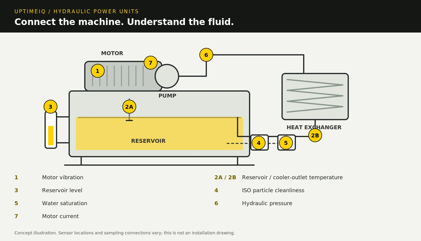
Concept illustration by UptimeIQ. Measurement locations are illustrative; final sensing and sampling arrangements are engineered for the power unit.
See the condition of your hydraulic power unit in one connected view.
A hydraulic power unit brings together a motor, pump, reservoir, filtration and cooling equipment. A hot reservoir, low fluid level, changing motor vibration or rising particle contamination may first appear as separate symptoms. Local gauges and periodic checks can leave gaps between observations. Maintenance teams need a shared view of the conditions that matter to each power unit, so they can investigate changes in context.
The UptimeIQ solution
UptimeIQ brings selected HPU measurements into custom cloud or on-premise dashboards. Vibration sensing follows the motor and suitable pump or bearing locations. Dedicated fluid-temperature measurements monitor the reservoir and the oil leaving the heat exchanger; an additional cooler-inlet measurement can provide useful comparison. Level sensing follows the reservoir, while a compatible particle sensor reports ISO 4406 cleanliness from a properly designed sampling point. A compatible water-saturation sensor separately follows moisture relative to the oil's saturation point, with temperature context. Hydraulic pressure and motor-current trends add operating context. Wired or wireless connections and the appropriate interfaces are selected for each measurement, with asset-specific trends, thresholds and alerts.
Follow the cooling circuit at the right points.
Reservoir temperature and heat-exchanger outlet temperature answer different questions. A dedicated fluid probe can monitor each point. Where a sensor measures a pipe or tank surface, its reading is a surface temperature and should not be presented as a direct fluid measurement. Comparing cooler inlet and outlet temperatures can help an investigation, with flow, load and cooling conditions considered alongside the readings.
Two fluid-health measurements. Two separate signals.
ISO particle cleanliness
A suitable contamination sensor follows particle cleanliness, expressed using ISO 4406 codes. Choose the target for the machine and its sensitive components; there is no single cleanliness target for every HPU.
Water saturation
A compatible moisture sensor follows relative water saturation and temperature. A rising saturation reading can prompt investigation. This is a separate measurement from particle cleanliness; it is not a direct water-content reading in ppm.
These measurements complement fluid analysis. Viscosity, chemical degradation and other fluid properties require their own sensors or laboratory tests. A condition alert calls for investigation and does not by itself mean that the oil must be changed.
From separate readings to a useful maintenance view.
- Define the HPU. Record its fluid, pressure range, reservoir, cooling circuit, motor and normal operating states.
- Choose the measurement points. Confirm safe access, process connections, fluid compatibility, sensor interfaces and suitable particle-sensor sampling conditions.
- Connect the readings. Bring the selected signals into UptimeIQ cloud or on-premise dashboards through compatible wired connections or wireless nodes.
- Set practical alerts. Use equipment guidance and operating baselines to configure thresholds, then review the trends when an alert occurs.
The complete HPU scope is engineered for your application. Fluid-temperature and fluid-condition channels may require additional sensor and interface selection beyond the Builder's standard packages. On-premise data hosting uses customer-supplied hosting hardware.
Manufacturer references: Banner hydraulic power unit monitoring · HYDAC cleanliness targets · HYDAC water-saturation sensing.
Seven measurements. One connected HPU view.
Motor vibration
Motor and suitable pump or bearing locations
Trend changes against an operating baseline. Select mounting and sensor capability for the machine and the maintenance objective.
Fluid temperature
Reservoir and oil leaving the heat exchanger
Use separate fluid measurement points to follow reservoir temperature and cooler-outlet conditions. Add cooler-inlet temperature when a comparison is useful; flow and load also affect cooling performance.
Reservoir level
A suitable reservoir measurement location
Follow fluid level and configured low/high limits. Select the sensing method for tank geometry, available access, fluid, foam and internal obstructions.
ISO fluid cleanliness
An engineered sampling or bypass connection
Trend ISO 4406 particle cleanliness against the machine's target. Confirm sensor compatibility, sampling pressure, flow and temperature; air or water can affect optical readings.
Water saturation
A suitable fluid sampling or circulation point
Track relative water saturation (% saturation) and fluid temperature using a compatible moisture sensor. Set fluid-specific limits; relative saturation is temperature-dependent and is not the same as water content in ppm.
Hydraulic pressure
Selected pump outlet, supply or other critical line
Follow pressure trends and high/low limits using a range that covers expected operation and spikes. Confirm the fluid and process connection.
Motor current
Selected motor supply conductor(s)
Add load context to vibration, pressure and temperature trends. One current transformer measures one conductor; current alone is not a complete energy measurement.
Measurement points, ranges, sampling rates and alert thresholds are selected for the HPU and its operating states. Monitoring supports maintenance decisions; it does not replace protective controls, interlocks or required inspections. Final system design and customer quotations require UptimeIQ engineering approval.
What the application delivers
- Bring mechanical condition and hydraulic operating data into a shared view
- Receive configured alerts for temperature, level, pressure, cleanliness and water-saturation changes
- Compare readings with operating load and maintenance history
- Support cooling, filtration and maintenance investigations with connected trends
Start with one critical hydraulic power unit. Share its normal pressure, fluid specification, reservoir dimensions, cooling arrangement and the conditions you want to monitor. UptimeIQ engineering can help define the measurement points and prepare a coordinated monitoring solution.
What would you like to monitor?
Tell us about your equipment, location, and the information your team needs.